
Adjustable Ground Mount Solar: Seasonal Tilt & ROI Guide
Understanding the Core Engineering of an Adjustable Ground Mount
In the rapidly maturing solar industry, the adjustable ground mount has evolved from a niche product into a mainstream engineering solution for utility-scale and commercial projects. Unlike fixed-tilt racking, an adjustable ground mount allows operators to manually or mechanically alter the tilt angle of the photovoltaic array.
This functionality is a strategic tool for maximizing solar irradiance capture as the sun’s altitude shifts dramatically between solstices. To see this engineering in action, explore premium options like the Solarmount X Series.
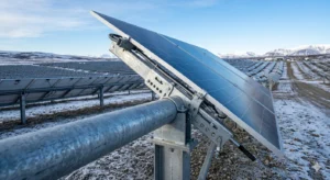
The fundamental architecture typically consists of a torque tube, tilting brackets, and a base structure anchored via driven piles or concrete ballasts. The defining feature is the multi-position hinge mechanism. High-end systems utilize a pinned connection with predefined angle settings—commonly at 15°, 30°, and 45°. This allows a single technician to adjust an entire row in minutes without heavy machinery. Maintaining torsional stability across a 90-meter-long row while allowing manual adjustment requires substantial engineering precision.
From a materials science perspective, premium manufacturers rely on high-strength low-alloy (HSLA) steels. These materials offer yield strengths exceeding 550 MPa. High strength is critical for resisting the bending moments induced by the cantilevered structure during adjustment.
Moreover, the galvanization standard is non-negotiable. We strictly recommend specifying G90 (Z275) or Magnelis-coated steel for installations in C3 or higher corrosive environments to ensure a 25-year structural lifespan without perforation corrosion.
Key Mechanical Components and Design Validation
The differentiation between a reliable adjustable ground mount and a catastrophic failure often lies in the locking pin assembly. Dynamic wind loads can induce micro-vibrations in poorly machined pins, leading to fatigue failure.
Top-tier designs incorporate a self-locking cam mechanism. This mechanism uses the panel’s weight to secure the tilt angle, eliminating shear stress on the bolt threads. Furthermore, Finite Element Analysis (FEA) must validate the structure against simultaneous wind uplift and gravitational dead loads at the maximum tilt angle, where the lever arm effect is most severe.
Seasonal Tilt Optimization: The Proven ROI of Adjustable Systems
The economic justification for deploying an adjustable ground mount hinges entirely on bifacial energy gains and seasonal albedo utilization. Fixed-tilt systems are optimized for a single “average” annual angle, which inherently sacrifices winter production when electricity prices often peak. By shifting from a summer angle of 15° to a winter angle of 45° (in mid-latitudes), an adjustable ground mount flattens the seasonal production curve.
Empirical data from the National Renewable Energy Laboratory (NREL) indicates that seasonal tilt adjustments yield a 4% to 7% annual energy increase compared to a fixed 20° tilt in regions above 30° latitude.
The true value proposition is the increase in specific yield (kWh/kWp) during winter months, which can spike by 15% to 20%. For power purchase agreements (PPAs) with time-of-day or seasonal multipliers, this winter boost significantly enhances the project’s internal rate of return (IRR).
It is also critical to factor in the bifacial gain multiplier. An adjustable ground mount inherently raises the module height at steeper tilts. This increases ground clearance and allows more reflected light to strike the rear side of bifacial modules. When albedo values exceed 0.3 (light sand or snow), the combination of high tilt and bifaciality creates a non-linear energy gain that fixed-tilt systems simply cannot replicate.
Quantifying the Energy Yield Differential
To understand the precise value, we analyze the Plane of Array (POA) irradiance. A fixed 20° system in Denver, CO, might capture 2,100 kWh/m²/year. A dual-adjustment schedule (summer/winter) on an adjustable ground mount can push this to 2,250 kWh/m²/year.
While the absolute difference seems modest, when applied to a 50 MW plant, the additional 150 kWh/m² translates to millions of dollars in revenue over the asset’s life. This far outweighs the incremental capital expenditure of the adjustable hardware. Learn more about optimizing your system configuration on our utility-scale mounting solutions page.
Structural Integrity and Wind/Snow Load Performance
Structural reliability is the paramount concern for any adjustable ground mount because variable geometry introduces complex aerodynamic behaviors. When the array is tilted at 45° or higher, it acts as a significant bluff body, dramatically increasing the drag coefficient. A system that passes wind tunnel tests at a 20° tilt may fail catastrophically at a 45° tilt if the structural engineering is not robust.
We must examine the torsional rigidity of the torque tube. In an adjustable ground mount, the tube must resist twisting from both static pressure and dynamic vortex shedding. The standard ASCE 7-22 wind load calculations must be applied specifically to the “worst-case” tilt angle, not the nominal operating angle. Look for systems that provide independent engineering stamps for each tilt configuration to validate that the purlin spacing and post embedment depth are sufficient.
Snow Shedding and Ground Clearance Dynamics
Snow load resilience is another area where the adjustable ground mount excels. The ability to shift to a near-vertical position (e.g., 60° or steeper) during a blizzard is a game-changer. By shedding snow rapidly, the structure avoids the massive static loads that crush fixed-tilt carports.
However, the design must account for eccentric loading during the shedding event. The sudden slide of a 500 kg snow slab creates a dynamic shock load that can shear bolts if the system lacks energy-dissipating clamps.
Comparative Analysis: Top Adjustable Ground Mount Manufacturers
Selecting the right adjustable ground mount requires a rigorous technical comparison. The market has consolidated around engineering-driven manufacturers who prioritize structural integrity over cost-cutting. Below is a comparative analysis based on published datasheets and field feedback from EPC contractors.
| Feature / Specification | Solarmount X (Adjustable Series) | Competitor A (Standard Adjustable) | Competitor B (Premium Adjustable) |
| Material Grade | Q355B HSLA Steel (550 MPa Yield) | Q235B Mild Steel (235 MPa Yield) | Q345B Steel (345 MPa Yield) |
| Corrosion Protection | Magnelis / G90 Hot-Dip Galvanized | Standard G60 Galvanized | G90 Pre-Galvanized |
| Tilt Adjustment Range | 10° – 60° (Infinite Pin-Lock) | 15° – 45° (3 Fixed Positions) | 10° – 55° (5 Fixed Positions) |
| Max Wind Speed Rating | 180 km/h (3-sec gust, 45° tilt) | 150 km/h | 160 km/h |
Foundation Compatibility and Geotechnical Considerations
An often overlooked aspect of adjustable ground mount design is foundation compatibility. The dynamic loads introduced during tilt adjustments require foundations that can resist vertical, lateral, and significant overturning forces. Driven piles remain the most common solution, offering high load capacity and rapid installation.
In rocky or environmentally sensitive sites, concrete ballasts or ground screws may be necessary. Each foundation type must be evaluated for its ability to handle the increased moment arm at steeper tilt angles.
Geotechnical surveys are critical. Soil bearing capacity, frost depth, and corrosion potential directly influence the design life of the system. For instance, expansive clay soils can exert uplift forces on piles during wet-dry cycles, compromising the tilt mechanism’s alignment. Therefore, we recommend a thorough geotechnical investigation compliant with ASTM International testing standards and, if needed, the use of helical piles or micro-piles to ensure long-term stability.
Installation Workflow, Labor Efficiency, and TCO
The installation of an adjustable ground mount system involves additional steps compared to fixed-tilt. However, advancements in pre-assembled components have significantly reduced labor hours. Key phases include foundation installation, torque tube assembly, module rail attachment, and tilt mechanism calibration. Modern systems feature color-coded angle indicators and quick-release pins, enabling a crew of three to adjust a 1 MW block in under two hours.
When evaluating these systems, the Total Cost of Ownership (TCO) must be considered over the project’s 25-30 year lifespan. The initial capital expenditure is typically 10-15% higher than fixed-tilt due to the more complex structure. However, this premium is quickly offset by increased energy production and a lower levelized cost of energy (LCOE).
-
Material costs: Higher-grade steel and corrosion protection add upfront cost but reduce replacement needs.
-
Installation labor: Slightly higher due to tilt calibration, but offset by faster module mounting with pre-assembled rails.
-
Maintenance: Annual inspections and occasional part replacements (pins, bushings) add approximately 0.5% of initial CAPEX per year.
-
Energy revenue gain: 4-7% annual increase, with winter peaks up to 20%, significantly improving project IRR.
For a 50 MW plant, the additional revenue from seasonal adjustment can exceed $2 million over the system’s life. This makes the adjustable ground mount a financially sound choice for developers focused on maximizing returns.