
Commercial Ground Mount Solar: 10 Critical Factors (2026)
The Strategic Imperative of Commercial Ground Mount Solar
Investing in a commercial ground mount solar system is fundamentally an exercise in structural finance and civil engineering. Unlike rooftop arrays, which are often constrained by azimuth and building-load limits, ground-mounted systems offer perfect orientation and optimal airflow. However, this design freedom introduces a complex matrix of variables—from soil mechanics to aerodynamic damping—that directly dictate the project’s Internal Rate of Return (IRR).
For developers, EPCs, and procurement officers, the mounting structure is not merely a passive steel skeleton; it is the active interface between the photovoltaic module and the terrestrial environment. This guide distills the selection process into 10 non-negotiable engineering and commercial factors to ensure a service life exceeding 25 years.
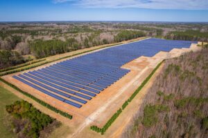
At a Glance: Key Considerations for Ground Mount Projects
| Consideration | Impact on LCOE | Priority Level |
| Structural Code Compliance | High (Failure Risk) | Critical |
| Geotechnical Validation | High (Cost Control) | Critical |
| Corrosion Protection | Medium (Longevity) | High |
| Bifacial Yield Modeling | Medium (Revenue) | High |
| Material/Supply Chain | Low (Upfront Cost) | Medium |
Structural Engineering: The Backbone of Performance
Structural integrity in commercial ground mount solar systems is defined by the ability to resist multi-directional load combinations without deformation. Design must adhere to ASCE 7-22 (Minimum Design Loads and Associated Criteria for Buildings and Other Structures) and AISC 360 (for steel construction).
Critical Design Parameters:
-
Deflection Limits: Purlin deflection must be $\le$ L/120 to prevent micro-cracking in PV cells.
-
Connection Rigidity: Bolted connections must be designed as slip-critical joints to combat fretting fatigue.
-
Buckling Analysis: Long-span posts require Finite Element Analysis (FEA) to verify global buckling resistance, especially in high-seismic zones.
Foundation Selection: The Geotechnical Bedrock
The foundation accounts for 15%–25% of the total structural budget. Selection is driven entirely by the geotechnical survey, which must identify friction angles, cohesion, and depth to bedrock.
Foundation Typology Decision Matrix
-
Driven Steel Piles (W6x9/C-channel): Optimal for cohesive soils.
-
Helical Piles: Preferred for expansive clays or low-bearing capacity soils.
-
Ground Screws: Ideal for sandy, low-vibration sites.
-
Precast Concrete Ballast: Necessary for capped landfills or geomembranes where soil penetration is prohibited.
Pro Tip: A rigorous pull-out and lateral load test program is non-negotiable to validate design assumptions before bulk procurement.
Corrosion Protection Strategies
Longevity is a race against oxidation. Specifiers must match the protective coating to the site’s environment, adhering to ASTM A123 (Standard Specification for Zinc (Hot-Dip Galvanized) Coatings).
-
Rural/Standard: G90 zinc coating (0.90 oz/ft²).
-
Coastal/Industrial: G140 or G210 coating mandatory.
-
Advanced Alternative: Zn-Al-Mg alloy coating (ZAM) offers superior self-healing cut-edge protection.
Always demand coating thickness measurements using magnetic induction gauges during incoming quality control.
Aerodynamic Load Management
Wind loading is the dominant lateral force for commercial ground mount solar. The array acts as a bluff body, making the system susceptible to vortex shedding and torsional instability.
-
Design Wind Speed: Derived from ASCE 7-22 maps, adjusted for topographic speed-up.
-
Snow Mitigation: In high-snow regions (>30 psf), prioritize multi-leg frame geometries over single-post cantilever designs.
Maximizing Energy Yield: Bifacial & Tilt Optimization
The advent of bifacial modules has shifted the optimization paradigm. Recent research from the NREL Bifacial PV Project demonstrates significant gains in rear-side capture when mounting parameters are optimized.
-
Row Spacing: Aim for a Ground Coverage Ratio (GCR) of 0.35–0.50.
-
Rear-Side Capture: Elevated mounting heights and optimized tilt angles can increase rear-side irradiance capture by 5% to 15%.
Financial Modeling: The LCOE Metric
The ultimate metric is the Levelized Cost of Energy (LCOE). Referencing the NREL Technology LCOE methodology, it is clear that higher initial capital expenditure often lowers LCOE by reducing O&M costs and improving system uptime over 25+ years.
-
Sensitivity Analysis: Perform analysis on steel prices, labor rates, and discount rates.
-
Long-Term Value: Investing in premium coatings may increase upfront costs by 5% but decrease maintenance costs by 20% over the asset lifetime.
Conclusion: Partnering for Project Success
Selecting a commercial ground mount solar system is a strategic decision that balances upfront engineering costs against long-term asset performance. By adhering to rigorous structural standards, validating foundations through geotechnical data, and focusing on LCOE rather than just the initial bid, stakeholders can deploy infrastructure that delivers reliable, low-cost energy for decades.
Ready to start your next commercial ground mount solar project?
[Contact the SolarMountX Engineering Team] for a feasibility assessment, stamped PE drawings, and site-specific load calculations.
Ground-Mount Engineering Guides
Use these guides to connect the ground-mount structure with operations, maintenance, foundation and RFQ decisions.
- Ground-mount solar O&M guide — inspection access, foundations, cable routes, corrosion and handover scope.
- Ground-mounted solar panel foundations guide — driven pile and concrete foundation inputs, site conditions and RFQ documents.
Related solar mounting guides: Large-scale solar racking selection guide · Solar farm mounting cost guide.